
Understanding Radiographic Artifacts: Common Artifacts and How to Avoid Them
Digital radiography is a cornerstone of veterinary medicine, but radiographic artifacts specific to digital imaging can create certain challenges. These artifacts can significantly compromise image quality, leading to misinterpretation and incorrect diagnoses. Being able to recognize artifacts and their causes is critical to correctly interpreting digital radiographs.
Digital radiography includes both computed radiography (CR) and direct digital radiography (DDR), where images are directly converted into digital images. CR requires a separate processing step, a plate reader, whereas all types of DDR instantaneously transfer data to a computer.
Radiographic artifacts arise from multiple stages of the imaging process, including during pre-exposure, exposure, postexposure, reading, and workstation activities. Understanding these errors and implementing corrective measures are essential steps to produce high-quality diagnostic images. 1,2
1. Pre-exposure Artifacts
Pre-exposure artifacts occur before the actual imaging process.
Computed Radiography:
- Storage scatter results from exposure to extraneous radiation sources, which can create noticeable patterns on the image. To prevent this, imaging plates should be stored away from radiation sources and erased before use.
- Cracks in imaging plates, often caused by physical damage during handling, appear as linear or focal white artifacts. Proper maintenance and careful handling of imaging plates can reduce the occurrence of cracks.
- Partial erasure and phantom images are due to incomplete erasure of previous images, avoided by ensuring thorough erasure of imaging plates before reusing.
Direct Digital Radiography:
- Memory artifacts are residual images from previous exposures due to retained charge in the detector. Allowing time between exposures can help dissipate this charge.
- Dead pixels result from nonfunctional detector elements and appear as white or black spots on a radiograph. Detector array mapping and postprocessing to cancel out dead pixels can help; however, replacing the detector array may be necessary.
- Calibration mask artifacts arise from variable attenuation during calibration, and the cause of variation will be imprinted on the radiograph. Cleaning equipment and recalibrating or recalibrating with table-top technique should eliminate artifacts.
2. Exposure Artifacts
These artifacts are related to the actual imaging process.
Computed Radiography:
- Upside-down cassette orientation leads to underexposed patterns due to X-rays passing through the back of the cassette. Ensuring correct cassette orientation before exposure can prevent this artifact.
- Backscatter occurs when X-rays scatter off objects behind the cassette and return to the imaging plate, creating nonuniform exposure patterns. Using cassettes with lead backing and reducing exposure settings can minimize backscatter.
Direct Digital Radiography:
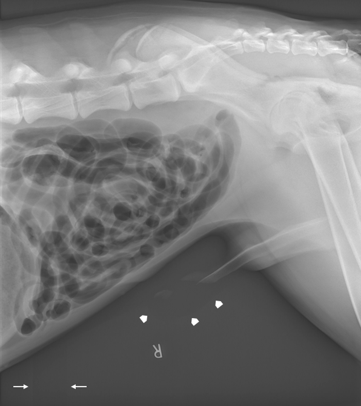
- Paradoxic overexposure effect causes grayscale reversal in areas of severe overexposure (Figure 1). Using techniques with increased X-ray penetration (higher kVp) and decreased total number of X-rays (lower mAs) can reduce this artifact.
- Planking is observed as rectangular planks and results from variable amplification of separate array sections (Figure 1). Decreasing the mAs and routine equipment calibration can help decrease planking. Planking is often seen with paradoxic overexposure effect.
Both CR and DDR:
- Grid cutoff results from incorrect positioning or orientation of the grid, leading to excessive reduction of incident X-rays. Proper placement and orientation of the grid are essential to avoid this artifact.
- Double exposure happens when imaging plates are used for multiple exposures without being read or erased between each one. Reading imaging plates immediately after exposure can prevent double exposures.
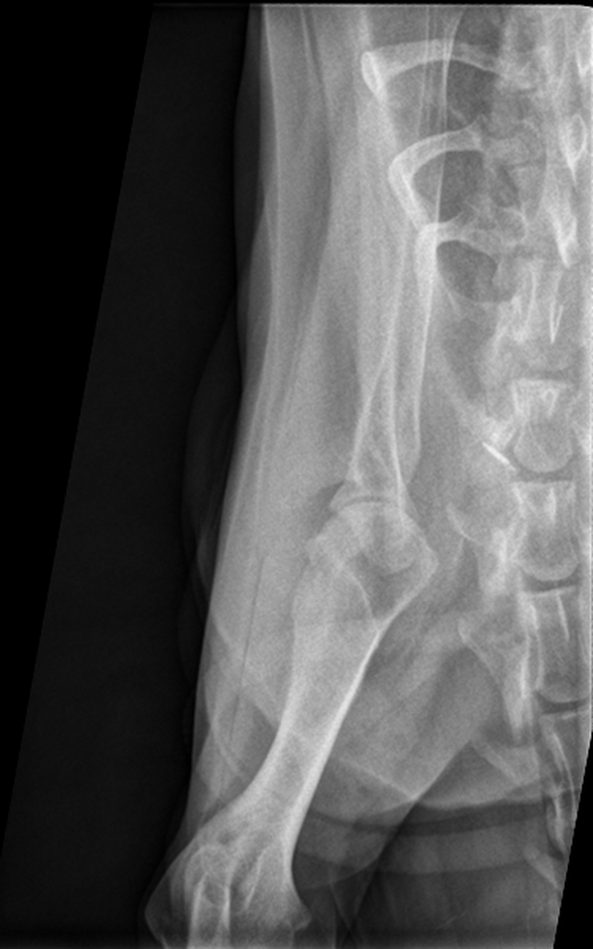
- Quantum mottle has a grainy appearance due to fluctuations in the number of X-ray photons (Figure 2). This can be reduced by using appropriate exposure techniques to increase the signal-to-noise ratio.
- Saturation occurs when the maximum storage capacity of the imaging plate or detector element is exceeded, resulting in completely black areas on the image. Reducing exposure levels can avoid saturation.
3. Postexposure Artifacts
Postexposure artifacts may occur after the actual imaging process.
Computed Radiography:
- Light leaks, imaging plates exposed to visible light after X-ray exposure but before reading, lead to uneven and incomplete erasure. Minimizing light exposure and maintaining cassette integrity are key.
- Fading, a white image, occurs when latent images are not read promptly, allowing the plate to return to a neutral state. Reading plates immediately after exposure is recommended.
4. Reading Artifacts
These artifacts are related to the process of reading the latent image from the imaging plate.
Computed Radiography:
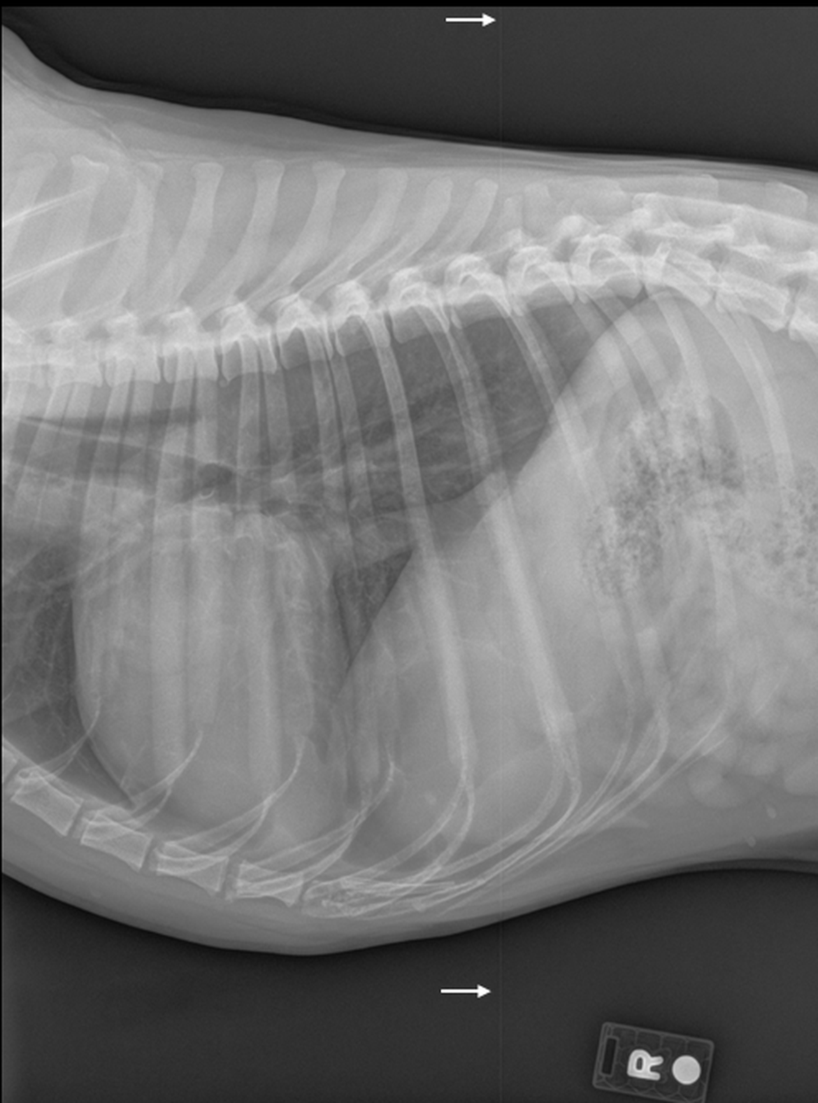
- Debris (Figure 3) and dirty light guide (Figure 4) artifacts are caused by debris or dirt blocks that emitted light and created white artifacts, dots, or lines on the image. Regular cleaning of plates and readers is essential.
- Skipped scan lines result from mechanical issues of the plate in the reader, leading to distorted images. Ensuring stable mechanics and power supply can help.
- Unequal phosphors artifacts occur when imaging plates and readers are mismatched, reducing image quality. Using compatible equipment is crucial.
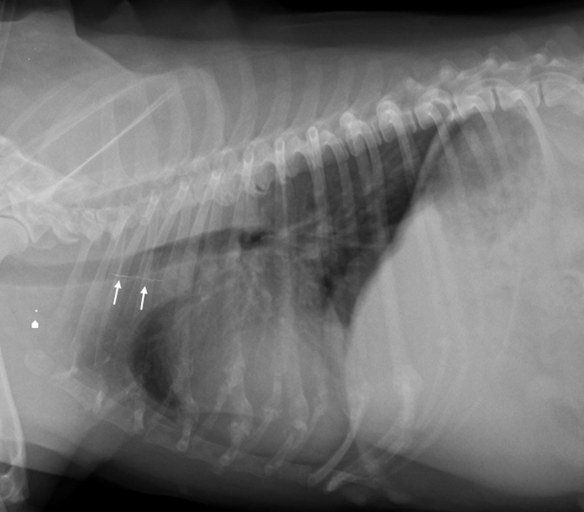
Figure 3: Lateral radiograph of a dog thorax. A linear metal opaque line is superimposed with the cranial mid mediastinum, marked by white arrows. A single pinpoint metal focus is present in the region of the thoracic inlet, marked by the white arrowhead. Both structures are examples of debris artifacts.
5. Workstation Artifacts
Workstation artifacts relate to issues caused by the physical workstation.
Both CR and DDR:
- Faulty transfer artifacts stem from data corruption during transfer, causing image distortion. Reliable hardware and software can prevent this.
- Border detection errors occur when the workstation misidentifies radiograph borders, potentially omitting important areas. Proper alignment and semiautomatic border detection can help.
- Diagnostic specifier artifacts result from incorrect selection of the area of interest, leading to poor postprocessing. Accurate area selection is necessary.
- Moiré patterns are interference patterns caused by grid and sampling frequency overlap. High-density, oscillating grids can decrease moiré artifacts.
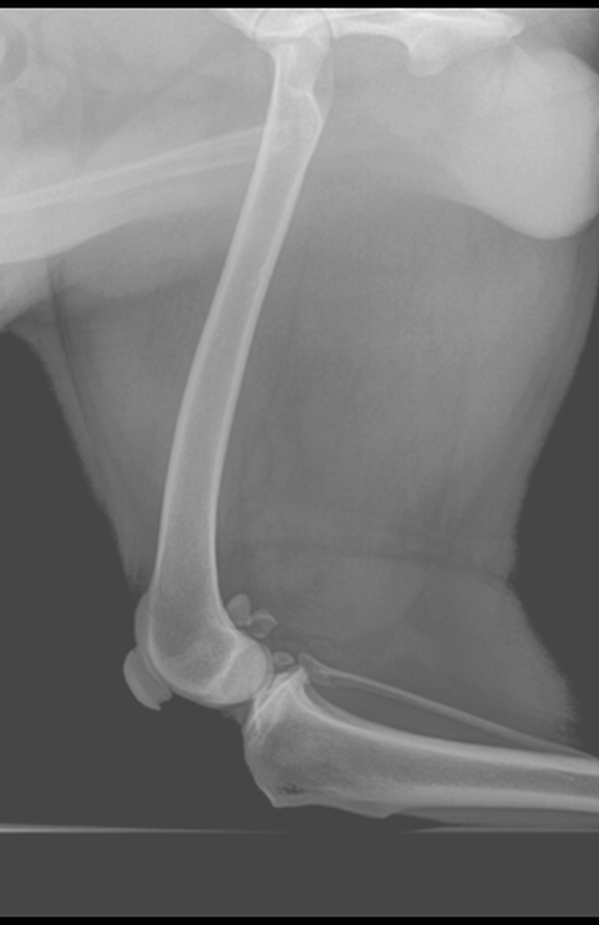
- Clipping artifacts occur when high-exposure areas are overprocessed, leading to complete darkening of areas of higher X-ray exposure (Figure 5). Customizing processing techniques for each radiographic study type can prevent clipping.
- Density threshold artifacts occur when objects of extreme density are included in histogram analysis, decreasing contrast between biologic tissues. Implementing density thresholds to exclude extremely dense objects can improve image quality.
- Überschwinger artifacts are caused by excessive edge enhancement and appear as thin black lines surrounding objects of higher attenuation (Figure 6). Using moderate amounts of edge enhancement can minimize überschwinger artifacts.
Knowledge Is Key to Avoid These Common Mistakes
Radiographic artifacts can significantly impact the diagnostic quality of images, leading to misinterpretation and incorrect diagnoses. By understanding the causes of these artifacts and implementing corrective measures, veterinarians can improve the quality of radiographic images and enhance their diagnostic capabilities.
Proper exposure, positioning, artifact management, and postprocessing are crucial steps in troubleshooting poor-quality images and ensuring accurate interpretation.
References:
- Jiménez DA, Armbrust LJ, O'Brien RT, Biller DS. "Artifacts in digital radiography." Vet Radiol Ultrasound. 2008 Jul-Aug;49(4):321-32. doi: 10.1111/j.1740-8261.2008.00374.x. PMID: 18720761.
- Jiménez DA, Armbrust LJ. "Digital radiographic artifacts." Vet Clin North Am Small Anim Pract. 2009 Jul;39(4):689-709. doi: 10.1016/j.cvsm.2009.04.002. PMID: 19531395.

